new and used avionics
 Sell Your Avionics Here
|
Avionics List
new and used avionics |
Sell Your Avionics Here
|
Buying Safety Tips |
Avionics Articles and Reviews
|
The Garmin GTX 327 Transponder
The GTX 327 transponder is Garmin's second general aviation transponder. Even before this "Review" I liked the new GTX 327 better. The huge display can't be overlooked and the counters are really nice. In fact, rumor has it other aircraft can read the large letters on this transponder . I didn't really care much for Garmin's first transponder. Let's dive into the new GTX 327 and see what makes it tick.
The GTX 327 does not employ a cavity. The
cavity is a tube inside the transponder. Even though the cavity isn't made of
glass; it is in fact a tube. Cavities are prone to fail after five years or so
and are very expensive to replace.
Cavity replacements often cost more than the value of the transponder.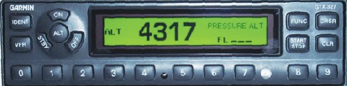 fortunately,
the boys at Garmin found a way to produce a solid-state transmitter capable of
producing around 200 watts (no cavity). Our bench test showed an output of 190
watts. Current draw was a skimpy 15 watts. The GTX 327 will run anywhere from
11-33 Vdc. No dropping resistor is required. The Maximum altitude for the GTX
327 is 50,000ft. If you need more altitude than the 50K, then give NASA a call.
Dimensions are 8.2"Lx6.25"Wx1.63"H. The 8.2" is short for a
transponder, thus making it a good choice in many homebuilts. This transponder
meets TSO C74c Class 1A. Garmin's brochure says the GTX 327 weighs 2.1 lbs but
my calibrated scales showed 2.65 lbs. Maybe my transponder needs to go on a
diet? Forced air-cooling is not required with the GTX 327 but Garmin recommends
it. I found forced air-cooling only cools the external heat sink of the
transmitter, thus dust does not get blown inside of the transponder. The GTX 327
via standard Gray Code or RS-232 accepts mode "C" "altitude
input". This transponder also has a RS-232 output for information to other
avionics such as the Garmin GNS 430. There's a squat switch input that will
start the automatic timer to start timing once the airborne and also places the
transponder in the "Standby" mode once the aircraft lands. This may
sound nice but this feature could be expensive to connect. Normally the FAA
wants to see a major alteration form completed anytime a shop ties into the
landing gear wiring. If I connected this feature, I'd use a separate air speed
switch or better yet, just push start button just before you take off. The GTX
327 backlighting can be set manually or by using the aircraft dimmer buss. The
dimmer circuit can be 5, 14 or 28Vdc. There is a "Switched power out"
that can fire up your encoder or whatever you desire as long at the current is
less than 1.5 amps. Garmin's installation manual is OK but leaves some areas
of the installation unexplained.
fortunately,
the boys at Garmin found a way to produce a solid-state transmitter capable of
producing around 200 watts (no cavity). Our bench test showed an output of 190
watts. Current draw was a skimpy 15 watts. The GTX 327 will run anywhere from
11-33 Vdc. No dropping resistor is required. The Maximum altitude for the GTX
327 is 50,000ft. If you need more altitude than the 50K, then give NASA a call.
Dimensions are 8.2"Lx6.25"Wx1.63"H. The 8.2" is short for a
transponder, thus making it a good choice in many homebuilts. This transponder
meets TSO C74c Class 1A. Garmin's brochure says the GTX 327 weighs 2.1 lbs but
my calibrated scales showed 2.65 lbs. Maybe my transponder needs to go on a
diet? Forced air-cooling is not required with the GTX 327 but Garmin recommends
it. I found forced air-cooling only cools the external heat sink of the
transmitter, thus dust does not get blown inside of the transponder. The GTX 327
via standard Gray Code or RS-232 accepts mode "C" "altitude
input". This transponder also has a RS-232 output for information to other
avionics such as the Garmin GNS 430. There's a squat switch input that will
start the automatic timer to start timing once the airborne and also places the
transponder in the "Standby" mode once the aircraft lands. This may
sound nice but this feature could be expensive to connect. Normally the FAA
wants to see a major alteration form completed anytime a shop ties into the
landing gear wiring. If I connected this feature, I'd use a separate air speed
switch or better yet, just push start button just before you take off. The GTX
327 backlighting can be set manually or by using the aircraft dimmer buss. The
dimmer circuit can be 5, 14 or 28Vdc. There is a "Switched power out"
that can fire up your encoder or whatever you desire as long at the current is
less than 1.5 amps. Garmin's installation manual is OK but leaves some areas
of the installation unexplained.
Let's talk about the installation kit and form, fit
and finish. Gamin's installation kits are some of the worst we have
to deal with and the GTX 327 is not an exception. Here are a few examples. There
are two sizes of pins for the connector. Four are longer than the others. I
couldn't find anywhere in the manual that shows which holes get the longer
pins. I'm sure it's the power and ground but I'd like to see that in
writing. The four long pins are the solder type but the rest require a crimping tool.
That's not a problem for an avionics shop but the homebuilder probably
doesn't have a $400.00 crimping tool in their toolbox.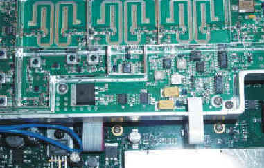 Be sure you slide the
right pin in the correct hole on the connector. If not, you will need a special
tool in order to remove the pins. Garmin does not give you any extra pins; screw
up one pin and you're hosed. Again, this isn't a problem for an avionics
shop but that homebuilder in a foreign country may get frustrated. Remember
those four long pins listed above. Due to the fact they are longer, these pins
do not fit well in the protective shell. The "D" connector does not
have nuts locked on the outer section of the connector. Garmin wants you to use
two long screws with nuts holding the connector on the other end. The
"D" connector is hard mounted to the back shell, thus it doesn't
move. This connector should "float" to assure the connector on the
transponder doesn't bind when installing in the rack. If the connector does
bind, something has to give. Rest assured, whatever gives will be expensive and
not under warranty. I noticed that screw holes in the transponder did not align
up with the nut plates inside, thus the screws looks like they were in crooked.
There needs to be a screw in the bottom, left rear corner of the transponder.
The cover does not fit properly without it. Now picture this. There are two
holes in the rack backing plate that has a hole in it. If you place a screw into
that hole it will tighten into the transponder cover. Now the transponder cover
properly seats on the transponder. The problem is now you can't get the
transponder out of the rack because of the screw goes through the backing plate
and into the transponder. Go figure. The cast bezel on the GTX 327 is excellent.
It fits and looks great. All the buttons on the front are centered on the holes
they extrude through. General layout of the buttons is good. This is a
transponder full of features that is so easy to operate you don't need the
operator's manual. I removed the cover to see what kind of magic was inside.
Inside of the GTX 327 is some of the best electronics layout I've ever seen.
No jumper wires or cut traces just quality looking PC board work. It's obvious
that the engineers who designed the electronics and ergonomics aren't the same
ones that design the install kits. In fact, I doubt if they are in the same
universe. Maybe I'm too picky on cosmetics and installation kits but I've
been around installation for 18 years and I know this company has the technology
to do better.
Be sure you slide the
right pin in the correct hole on the connector. If not, you will need a special
tool in order to remove the pins. Garmin does not give you any extra pins; screw
up one pin and you're hosed. Again, this isn't a problem for an avionics
shop but that homebuilder in a foreign country may get frustrated. Remember
those four long pins listed above. Due to the fact they are longer, these pins
do not fit well in the protective shell. The "D" connector does not
have nuts locked on the outer section of the connector. Garmin wants you to use
two long screws with nuts holding the connector on the other end. The
"D" connector is hard mounted to the back shell, thus it doesn't
move. This connector should "float" to assure the connector on the
transponder doesn't bind when installing in the rack. If the connector does
bind, something has to give. Rest assured, whatever gives will be expensive and
not under warranty. I noticed that screw holes in the transponder did not align
up with the nut plates inside, thus the screws looks like they were in crooked.
There needs to be a screw in the bottom, left rear corner of the transponder.
The cover does not fit properly without it. Now picture this. There are two
holes in the rack backing plate that has a hole in it. If you place a screw into
that hole it will tighten into the transponder cover. Now the transponder cover
properly seats on the transponder. The problem is now you can't get the
transponder out of the rack because of the screw goes through the backing plate
and into the transponder. Go figure. The cast bezel on the GTX 327 is excellent.
It fits and looks great. All the buttons on the front are centered on the holes
they extrude through. General layout of the buttons is good. This is a
transponder full of features that is so easy to operate you don't need the
operator's manual. I removed the cover to see what kind of magic was inside.
Inside of the GTX 327 is some of the best electronics layout I've ever seen.
No jumper wires or cut traces just quality looking PC board work. It's obvious
that the engineers who designed the electronics and ergonomics aren't the same
ones that design the install kits. In fact, I doubt if they are in the same
universe. Maybe I'm too picky on cosmetics and installation kits but I've
been around installation for 18 years and I know this company has the technology
to do better.
Just how good is the GTX 327 display? Well, if you can't see this display you should apply for some type of disability. It's huge and bright. I found that anywhere in the radio stack I placed the GTX 327 it was easily visible. This should be a great transponder for the A-36 and sorts where the transponder is located far on the right side of the aircraft. One could easily install the "Remote Ident" so the pilot could ident the transponder by pushing a button on the switch. Lighting intensity and back lighting can be controlled via software, or automatically by the photocell located in the front of the unit. Lighting can also be controlled by the aircraft dimmer buss. I found the photocell did a fine job. As the aircraft gets dark inside, the black letters and yellow background will start to dim. At a programmed level, the letters will turn yellow and the background black. This feature worked great during my evaluation of this product. Minimum dimming levels are set via software. The display shows your mode "A" code, pressure altitude, mode of operation; count up or down timer and flight timer. More on these later. As you would expect the display presents the usual "reply", "ident", "and mode "such as" Alt".
Now let's discuss the buttons on the GTX 327
faceplate. Once the avionics master switch is turned on the pilot
would normally press the ""ALT" button. This turns on the
transponder and after about nine seconds the transponder is up and running in
both mode A and C. Should the pilot not wish to turn on mode C (this is
altitude) simply press the "ON" button. There is a "STBY"
which fires up the transponder but inhibits the GTX 327 from replying to
interrogations. Unlike what I call manual transponders (transponders which have
knobs on them) the GTX 327 does not come alive when the avionics master switch
is turned. The pilot must push a button on the transponder in order to wake it
up. Because this transponder needs no warm-up time this is not a problem. To
turn off the transponder simply press the "OFF" button and hold for
about two seconds. Along the bottom of the transponder faceplate are the digits
0-9. If ATC gives you the code of 2-3-4-6, simply press those keys and the
display will change to that new code. If you error while keying in a code, just
press the "CLR" button and the cursor will move back to the prior
digit and you can correct it. This is true only if you have "Pressure
Alt" displayed. If you have any of the timer functions selected pressing
the "CLR" button does nothing. If you do press in an incorrect digit,
the only way to correct the problem is to press "CRSR" and start all
over. All four digits must be entered before the new code is transmitted. If you
really get messed up, just press the "CRSR" button and that cancels
out everything plus restores your previous code. The (8) and (9) button cannot
be entered in a code, only 0-7. We will use all the buttons when playing around
with the timers. By
pressing the "IDENT" button an ident pulse will be sent to ATC for 18
seconds. The display will illuminate the "IDENT" while the ident pulse
is present. Press the "VFR" button and code will automatically change
to 1200. Pressing the "FUNC" button changes the pages shown on the
right of the display. Displayed data includes Pressure Altitude, Flight Timer,
Count Up Timer and a Count Down Timer. Oh, before I forget. The "VFR"
code can be changed to read whatever you desire when you press the "VFR"
button. My understanding is some countries use 7000 as a VFR code. One can
easily program the GTX 327 to display that or any other code. Also the altitude
can be set the pressure altitude to readout in meters. These are excellent
features for the pilot who flies to different countries or is based in a country
that uses the mill bar scale.
If you error while keying in a code, just
press the "CLR" button and the cursor will move back to the prior
digit and you can correct it. This is true only if you have "Pressure
Alt" displayed. If you have any of the timer functions selected pressing
the "CLR" button does nothing. If you do press in an incorrect digit,
the only way to correct the problem is to press "CRSR" and start all
over. All four digits must be entered before the new code is transmitted. If you
really get messed up, just press the "CRSR" button and that cancels
out everything plus restores your previous code. The (8) and (9) button cannot
be entered in a code, only 0-7. We will use all the buttons when playing around
with the timers. By
pressing the "IDENT" button an ident pulse will be sent to ATC for 18
seconds. The display will illuminate the "IDENT" while the ident pulse
is present. Press the "VFR" button and code will automatically change
to 1200. Pressing the "FUNC" button changes the pages shown on the
right of the display. Displayed data includes Pressure Altitude, Flight Timer,
Count Up Timer and a Count Down Timer. Oh, before I forget. The "VFR"
code can be changed to read whatever you desire when you press the "VFR"
button. My understanding is some countries use 7000 as a VFR code. One can
easily program the GTX 327 to display that or any other code. Also the altitude
can be set the pressure altitude to readout in meters. These are excellent
features for the pilot who flies to different countries or is based in a country
that uses the mill bar scale.
The aircraft encoder output is displayed in the right hand side of the GTX 327 display and is based on pressure altitude. I'm sure you remember how to get your altimeter to read pressure altitudeJ Press the "FUNC" key and the display now reads "Flight Time". The Flight Timer can be started or stopped via an airspeed switch or pressing the "Start/Stop" button on the GTX 327. To reset the Flight Timer simply press the "CLR" button. Press the "FUNC" button again and the "Count Up Timer" will appear. This feature is really handy for timing approaches. This nice feature is controlled via the "Start/Stop" and the "CLR" button. The next item on the "FUNC" list is the "Count Down" timer. To enter a time the in the Count Down timer press the "CRSR" button. The far left unit will now be high lighted. Now press any number 0-9. The curser will automatically move to the next character. Continue entering the count down number you desire. I found the pilot couldn't enter an invalid time. I tried to enter 89 minutes but the GTX 327 made me enter this time as 1 hour and 29 minutes. These features are easy to use and require very little thought process.
Is the push button GTX 327 easy to use while flying? Yes it is. During my test flight I found the buttons were easy to push even while getting bounced around. The timers were easy to set and only took seconds to do so. The display is as bright and easy to see as Rudolph's bright nose. The GTX 327 is a great, easy to operate, easy to read transponder and that's just what a transponder should be. This transponder would be at home in any aircraft. List Price is $1,895.00 and the GTX 327 comes with a one-year factory warranty.